introduction
In the processing of grain and oil machinery, there are many parts with a length to diameter ratio of l/d>20. For example: the main rotating shaft of the high square screen, the butterfly rotating shaft of the butterfly cylinder finishing machine, and the like. Such parts are often referred to as elongated shafts. Such parts are typically machined on a lathe. During the turning process, due to its poor rigidity, the slender shaft is prone to bending deformation under the action of cutting force and cutting heat, thus destroying the accuracy of the relative motion of the tool and the part, resulting in the produced elongated shaft. The middle of the thick, two-headed shape seriously affects the machining accuracy of the part. At the same time, the bending of the slender shaft causes the vibration of the process system and affects the roughness of the part.
1 Factors causing bending deformation of the elongated shaft
There are two main types of conventional clamping methods for turning an elongated shaft on a lathe: one way is that one end of the elongated shaft is clamped by a chuck, and the other end is supported by a top end of the lathe tailstock (one clip and one top); One way is that both ends of the elongated shaft are supported by the top (double top). The author mainly analyzes the clamping method of one clip and one top. The mechanical model is shown in Figure 1.
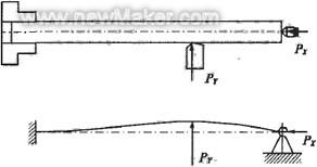
Figure 1 One clip and one top clamping method and mechanical model
Through analysis and research, the main reasons for the bending deformation of the slender shaft are:
1) Cutting force causes deformation
During the turning process, the generated cutting force can be decomposed into an axial cutting force PX, a radial cutting force PY, and a tangential cutting force PZ. Different cutting forces have different effects on the bending deformation when turning the elongated shaft.
The influence of radial cutting force PY
The radial cutting force acts vertically in the horizontal plane through the axis of the elongated shaft. Due to the poor rigidity of the elongated shaft, the radial force will bend the elongated shaft to cause bending deformation in the horizontal plane. Radial The effect of cutting force on the bending deformation of the elongated shaft is shown in Figure 1.
Effect of axial cutting force PX
The axial cutting force acts in parallel on the axis of the elongated shaft and forms a bending moment on the workpiece. For general turning operations, the axial cutting force has little effect on the bending deformation of the workpiece and can be ignored. However, due to the poor rigidity of the elongated shaft, the stability is also poor. When the axial cutting force exceeds a certain value, the elongated shaft will be bent and longitudinally bent and deformed. as shown in picture 2.
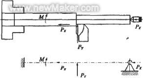
Figure 2 Effect of axial cutting force and mechanical model
2) Influence of cutting heat
The cutting heat generated by turning causes the workpiece to thermally elongate. Since the chuck and the tailstock tip are fixed during the turning process, the distance between the two is also fixed. Thus, the axial elongation of the elongated shaft after being heated is limited, causing the elongated shaft to be axially pressed to cause bending deformation.
Therefore, it can be seen that the problem of improving the machining accuracy of the elongated shaft is essentially the problem of controlling the force and deformation of the process system.
2 Measures to improve the machining accuracy of the slender shaft
In the process of slender shaft machining, in order to improve the machining accuracy, different measures are taken according to different production conditions to improve the machining accuracy of the elongated shaft.
1) Choose the right clamping method
In the two traditional clamping methods used for turning the slender shaft on the lathe, the double-tip clamping is adopted, the workpiece is positioned accurately, and the coaxiality is easily ensured. However, the slender shaft is clamped by this method, and the rigidity thereof is poor. The elongated shaft has large bending deformation and is easy to generate vibration. Therefore, it is only suitable for installation with small aspect ratio, small machining allowance and coaxiality requirement. High workpiece.
The processing of the slender shaft is usually carried out by means of a clip and a top. However, in the clamping mode, if the top is too tight, in addition to the possibility of bending the elongated shaft, it can also hinder the elongation of the elongated shaft during turning, causing the elongated shaft to be axially pressed and bent. Deformation. In addition, the clamping surface of the jaw and the hole of the tip may be different axes, and the positioning may occur after clamping, which may also cause bending deformation of the elongated shaft. Therefore, when using a clip and a top clamping method, the top should adopt a flexible living top. The elongated shaft can be freely elongated after being heated to reduce its thermal bending deformation; at the same time, an open bead ring can be inserted between the claw and the elongated shaft to reduce the axial contact length between the claw and the elongated shaft, thereby eliminating Over-positioning during installation reduces bending deformation. As shown in Figure 3.
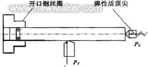
Figure 3 Improvement of a clip-top mounting method
2) Directly reduce the deformation of the elongated shaft
Using the tool holder and the center frame
In order to reduce the influence of the radial cutting force on the bending deformation of the elongated shaft, the bracket and the center frame are conventionally used, which is equivalent to adding a support to the elongated shaft. The rigidity of the elongated shaft is increased, and the influence of the radial cutting force on the elongated shaft can be effectively reduced.
Turning the slender shaft with axial pull-clamp
The use of the tool holder and the center frame, while increasing the rigidity of the workpiece, substantially eliminates the influence of the radial cutting force on the workpiece. However, the problem of the axial cutting force pressing the workpiece can not be solved, especially for the elongated shaft with a large long diameter, and the bending deformation is more obvious. Therefore, the axial shaft can be used to turn the elongated shaft. Axial clamping and turning means that one end of the elongated shaft is clamped by the chuck during the turning of the elongated shaft, and the other end is clamped by a specially designed clamping head, and the clamping head applies an axial pulling force to the elongated shaft. As shown in Figure 4.
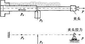
Figure 4 Axial pinch turning and mechanical model
During the turning process, the slender shaft is always subjected to the axial pulling force, which solves the problem that the axial cutting force bends the elongated shaft. At the same time, under the action of the axial tensile force, the bending deformation of the elongated shaft due to the radial cutting force is reduced; the axial elongation due to the cutting heat is compensated, and the rigidity and processing of the elongated shaft are improved. Precision.
Turning the slender shaft with reverse cutting
The reverse cutting method means that during turning of the slender shaft, the turning tool is fed from the spindle chuck to the tailstock, as shown in Fig. 5.
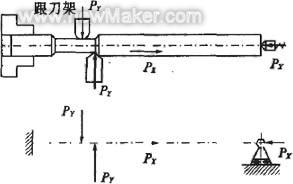
Figure 5 Reverse cutting machining and mechanical model
Thus, the axial cutting force generated during the machining causes the elongated shaft to be pulled, eliminating the bending deformation caused by the axial cutting force. At the same time, the elastic tailstock tip can effectively compensate the compression deformation and thermal elongation of the workpiece from the tool to the tailstock section, and avoid the bending deformation of the workpiece.
The double-tool turning slender shaft is used to modify the slide in the lathe, and the rear tool holder is added. The front and rear two turning tools are used for turning at the same time, as shown in Fig. 6.
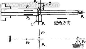
Figure 6 Double-knife machining and mechanical model
Two turning tools, diametrically opposed, the front turning tool is installed, and the rear turning tool is reverse mounted. The radial cutting forces generated when the two turning tools are turned are offset each other. The workpiece is subjected to force deformation and vibration, and has high processing precision, and is suitable for mass production.
Cutting the slender shaft with magnetic cutting
The principle of the magnetic cutting method is basically the same as the principle of the reverse cutting method. During the turning process, the elongated shaft is subjected to the magnetic stretching effect, which can reduce the bending deformation during the processing of the elongated shaft and improve the processing precision of the elongated shaft.
3) Reasonably control the amount of cutting
Whether the cutting amount is selected is reasonable, and the amount of cutting force generated during the cutting process and the amount of cutting heat are different. Therefore, the deformation caused when turning the elongated shaft is also different.
Cutting depth (t)
Under the premise of determining the rigidity of the process system, as the cutting depth increases, the cutting force and cutting heat generated during turning increase, and the stress and deformation of the elongated shaft also increase. Therefore, when turning the slender shaft, the cutting depth should be minimized.
Feed rate (f)
An increase in the feed rate increases the cutting thickness and increases the cutting force. However, the cutting force is not proportionally increased, so the force deformation coefficient of the elongated shaft is decreased. If the cutting efficiency is improved, it is advantageous to increase the feed amount rather than increase the depth of cut.
   With the continuous innovation and breakthrough of numerical control technology, five-axis machining has been adopted by more and more industries, such as aerospace, electric power, marine, high-precision instruments, mold manufacturing and so on. However, the automatic programming software plays a key role in the five-axis machining technology, because the process layout of the tool path, the interference check between the tool chuck and the workpiece or the fixture, and the identification of the residual amount of the blank are automatically considered by the software. Programmers can't do it through calculations. They just optimize the cutting parameters based on experience to get a more reasonable and effective machining path.
Cutting speed (v)
Increasing the cutting speed helps to reduce the cutting force. This is because, as the cutting speed increases, the cutting temperature increases, the friction between the tool and the workpiece decreases, and the stress deformation of the elongated shaft decreases. However, if the cutting speed is too high, the elongated shaft is bent under the centrifugal force and the smoothness of the cutting process is destroyed, so the cutting speed should be controlled within a certain range. For workpieces with large long diameters, the cutting speed should be appropriately reduced.
4) Choose a reasonable tool angle
In order to reduce the bending deformation caused by turning the slender shaft, it is required that the cutting force generated during turning is as small as possible, and in the geometrical angle of the tool, the rake angle, the main declination and the blade inclination have the greatest influence on the cutting force.
The rake angle (γ) directly affects the cutting force, cutting temperature and cutting power. Increasing the rake angle can reduce the degree of plastic deformation of the metal layer to be cut and the cutting force is significantly reduced.
Increasing the rake angle can reduce the cutting force. Therefore, in the slender shaft turning, under the premise of ensuring sufficient strength of the turning tool, the rake angle of the tool is increased as much as possible, and the rake angle is generally taken as γ=15°.
The lead angle (kr) affects the size and proportional relationship of the three cutting component forces. As the lead angle increases, the radial cutting force decreases significantly, and the tangential cutting force increases from 60° to 90°. In the range of 60 ° ~ 75 °, the ratio of the three cutting components is reasonable. When turning a slender shaft, a lead angle greater than 60° is generally employed.
The inclination angle of the blade inclination (λs) affects the flow direction of the chip during the turning process, the strength of the tool tip and the proportional relationship of the three cutting component forces. As the blade inclination increases, the radial cutting force decreases significantly, but the axial cutting force and the tangential cutting force increase. The blade inclination angle is in the range of -10° to +10°, and the proportional relationship of the three cutting component forces is reasonable. When turning a slender shaft, it is often used with a positive rake angle of +3° to +10° to allow the chips to flow to the surface to be machined.
3 Conclusion
Turning of slender shafts is a common processing method in machining. Due to the poor rigidity of the slender shaft, the force and heat deformation generated during turning are large, and it is difficult to ensure the processing quality requirements of the elongated shaft. Through the use of appropriate clamping methods and advanced processing methods, the selection of reasonable tool angle and cutting amount can ensure the processing quality requirements of the slender shaft.
Tile Insert Floor Drain,Tile Insert Floor Drain Cover,Tile Insert Stainless Steel Floor Drain,Black Linear Tile Insert Floor Drain
Kaiping City Jinqiang Hardware Products Co.,Ltd , https://www.kimpowerdrain.com