Plate chain transportation is the main form of automobile welding assembly adjustment line. It is an important tooling equipment in the automobile welding shop and an important factor to ensure the quality and appearance of the vehicle. The plate chain has high requirements on the strength, rigidity and running stability of each component. Reasonable design and accurate installation are of great significance to ensure the quality of the vehicle body and improve the operating efficiency of the equipment.
Composition of the chain conveyor system
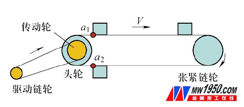
The chain conveyor system (see Figure 1) consists mainly of the following:
(1) Drive unit The drive unit, also known as the drive station, is a component that powers the conveyor line, including the motor, reducer and reducer sprocket.
(2) Head wheel device The head wheel device, also known as the drive shaft assembly, is the core part that connects the drive assembly and the conveyor chain plate, and functions to transfer the power provided by the drive assembly to the chain plate.
(3) Tensioning device Also known as the tensioning shaft assembly, it is similar to the head axle assembly except that there is one transmission sprocket smaller than the head axle, which is located at the other end of the head axle, and functions to tension the chain chain chain plate.
(4) Drive frame is a steel frame structure that supports the fixed head wheel device to support, fix and connect.
(5) Tensioning skeleton Similar to the driving skeleton, it functions to support, fix and connect the tensioning device.
(6) Conveying chain The head wheel axle sprocket and the tensioning shaft sprocket of the wire body cooperate with each other, which is a link connecting the entire wire body and is a main component for transmitting power.
(7) Transmission chain The chain connecting the reducer sprocket and the drive sprocket transmits the power of the drive unit to the line body.
(8) Conveyor chain plate The rectangular steel plate mounted on the chain is a carrier for supporting the wire body clamp (or horse stable).
(9) Other institutions include chain running track, lubrication device, protective device and electronic control system.

Figure 1 Schematic diagram of plate chain movement
Design process and requirements
Center distance determination
According to the station spacing and the effective number of work stations, the chain used, as well as the pitch of the sprocket, the number of sprocket, the number of teeth and the corresponding sprocket radius are determined. Calculate the center distance according to the above parameters and process parameters. It should be noted that the determined chain length must be an integral multiple of the station spacing, and the length of the circumferential part of the sprocket must also be an integral multiple of the station spacing. Consider the factors such as energy saving and consumption reduction, etc. The length of the circumferential portion of the wheel is generally double the spacing of the stations.
2. Drive design
1) The motor uses three-phase asynchronous motor and frequency conversion speed regulation.
2) The reducer must use a helical gear reducer to ensure the smooth running of the line body.
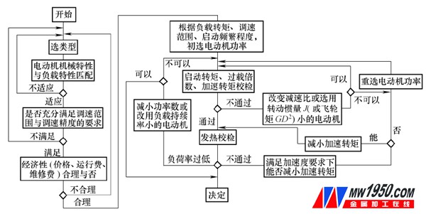
The choice of motor and reducer power is determined by the calculated value, and the final determined motor power is greater than the calculated value and is closest to the calculated value (see Figure 2).
3) The motor power is selected to meet the total power required for the operation of the line.
4) The drive unit and the head wheel unit are directly driven by the chain. The model selection of the drive chain and the reducer sprocket must conform to the national and mechanical industry standards.
5) The motor frame is connected to the head wheel bracket as a whole, and the skeleton is reinforced.
3. Head wheel device
1) The head axle adopts the integral solid shaft, 45 steel, and the quenching and tempering treatment ensures that the phase angles of the two wheels are equal.
2) The sprocket adopts 45 integral cast steel, the sprocket pitch meets the national and mechanical industry standards, and the center distance of the line body must be an integral multiple of the sprocket chain pitch.
3) The safety shear pin is designed according to the tension of the chain of the plate. The cutting diameter is four groups, and the cutting hole is two groups (a set of spare).
4) The bearing adopts double row spherical roller bearing, the model meets the national and mechanical industry standards.
4. Tensioning device
1) The tensioning device uses the slider seat to support the tensioning shaft, and the tension is completed by dragging the screw and the nut. The tensioning seat should have sufficient strength, the tensioning screw should be tensioned to the same extent, and the steel spring should be added for the elastic tension of the thermal expansion and contraction chain. The screw end sleeve contains a thrust bearing to reduce the tightening torque.
2) The sprocket adopts 45 integral cast steel, the tooth surface is quenched, the pitch is in line with the national and mechanical industry standards, and the sprocket and shaft are equipped with a single row of centripetal seals with ball bearings.
5. Conveyor chain
The chain adopts a single ear plate structure, the ear plate material is 45 steel or 40Cr, the quenching and tempering is black, and the chain meets the national and mechanical industry standards. The middle roller is equipped with two single-sided deep groove ball bearings with sealing rings. The gap between the roller and the inner chain plate is 2mm, and the chain and the pin shaft are heat-treated. Each group of bearings is filled with No. 2 lithium grease.
6. conveyor chain plate
The conveyor chain plate is a steel plate frame structure, the top plate is a pattern steel plate, and the lower part is an outsourced standard cold-formed inner crimping channel steel. The middle part is to have a reinforcing rib made of a flat steel plate, and the connection mode is welding, and the gap of the table top is not more than 5 mm. The connection between the conveying panel and the traction chain is made of bolts not lower than the strength of the national standard M10. The load bearing panel is reinforced.

Figure 2 Motor and reducer selection process
Installation requirements
The installation of a single unit and the entire line shall be carried out in accordance with the following installation specifications. The specific requirements are as follows:
1) The symmetry center line of the track and the longitudinal center line of the plate chain should coincide, and the deviation value is ≤ 2 mm.
2) The deviation of the center distance of the guide rail should be <2mm.
3) The straightness of the guiding surface of the guide rail is ≤1μm; the total length of the straight section is ≤3mm; the joint of the guiding surface should be smooth, and the amount of misalignment (should be low to the moving direction) should be ≤0.5mm.
4) The vertical deviation of the inner side of the guide rail is ≤10μm.
5) The symmetry center of the track of the wheel, the deviation of the center of the symmetry of the guide rail is ≤ 2mm; the deviation of the track of the track is ≤ 2mm.
6) The longitudinal horizontality of the plane on the track is ≤1/1500. The height deviation of the two guide rails at the same position is <0.5mm; the corner is only allowed to decrease toward the center of the curvature.
7) The height deviation of the whole line is ≤±5mm.
8) The linearity of the track orbit is ≤1/1000, and the total length of the straight line segment is ≤3mm.
9) The distance between the guide rail and the rail joint is less than 300mm from the sleeper; the joint is not allowed in the curved section, and the temperature extension joint should be left at the joint of the straight section. In the summer installation (40°C), the gap value is 1mm/10m; During installation (0 ° C), the gap value is 5 mm / 10 m; the deviation of the plane and the left and right misalignment on the adjacent track at the joint is ≤ 0.3 mm (only allowed to decrease in the direction of motion).
10) The curved section of the track and guide rail has a surface profile of ≤ 2 mm, and no convex deviation is allowed; the curved section and the straight section should be tangent and tangent.
11) The center line of the rack and the center line of the assembly line should coincide, the deviation perpendicular to the center line is ≤ 2mm, the straightness deviation of the center line of the rack is ≤ 1mm/m, and the difference between the cross-section of the frame cross-section is ≤ two diagonal average Long 1/1000, maximum ≤10mm.
12) The deviation of the bracket from the vertical of the building floor is ≤ 2/1000.
13) Drive the axle, the allowable difference of the level of the tensioning axle is ≤ 0.5/1000.
14) The chain should be installed straight and tight.
Debugging method
Equipment commissioning is also called commissioning. The purpose is to test the construction quality of the various processes in the early stage, and also to find problems in the design and manufacture of the entire equipment. The test run is to run the stationary equipment to further discover the problems in the equipment, and then make the final adjustment process to make the operation characteristics of the equipment meet the production needs. Therefore, commissioning is an important task in equipment installation and must be done:
1) Perform a full line inspection of the installed equipment, especially to check whether the electrical wiring is correct, whether the mechanical connection is reliable, and whether the rotating part is flexible.
2) Before operation, the reducer should be filled with clean lubricating oil. The surface of the full-line traction chain roller should be coated with lubricating oil. At the time of trial operation, pay attention to the oil level change and replenish the lubricating oil in time. Inject 40# oil into the tensioned bearing and inject it regularly during normal use.
3) After the tensioning device is adjusted, the traction member should have uniform and necessary force for normal operation, and the remaining tensioning stroke should not be less than 50% of the total stroke.
4) No-load test.
5) First, jog several times to confirm that the running direction is correct, and there is no stuck phenomenon in the movement before the test can be officially started. The test speed is the low speed of the design speed and the operation is 2h.
6) Load test. After the no-load test is completed, the load test can be carried out. The load test is carried out in three stages: the first stage loads 50%, the operation is at least not less than one cycle; the second stage loads 100%, runs 1h; the third stage loads 110 %, run at least one cycle.
7) During operation, check whether the equipment meets the basic design elements. If abnormality is found during operation, stop operation immediately, check and repair, and operate after the fault is removed.
Conclusion
The design and installation of the welding plate chain conveyor system must follow the principles of energy saving, environmental protection, safety and ease of maintenance. It should be stable, uniform and without jamming during the chain transportation, so the motor, reducer, chain, sprocket and Components such as rails have higher performance requirements, and the process requirements for the mounting and fitting of each component should be refined.
Amusement Lighting,Waterproof Led Amuserment Pixel Point Light,Led Pixel Amusement Lighting,Full Color Light Led
Shen zhen SH LED Technology Co.,Ltd , https://www.pixellightsolutions.com