Specification:Â
| Style: | Door Contact Alarm System Electric Magnetic Read Switch | Item: | BS-2011 |
| Color: | White, Brown, Grey | Material: | ABS |
| Cable: | Side leads with #22AWG 18" length | Loop Type: | closed |
| Reed Form: | N/O | Colsed Gap[Inch(mm)] | 1 (25) |
| Depature Gap[Inch(mm)] | 1.06 (27) | Maximum InitialContact Resistance(Ohm) | 0.150 |
| MaximumContact Rating(W) | 10 | Maximum Switching Voltage(VDC/VAC) | 100 |
| Maximum Switching Current(A) | 0.5 | Certificate | CE |
Door Contact Alarm System Electric Magnetic Read Switch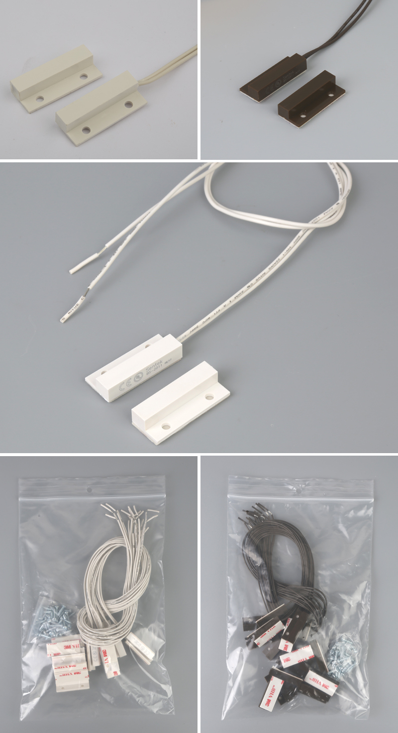
Dimension (mm):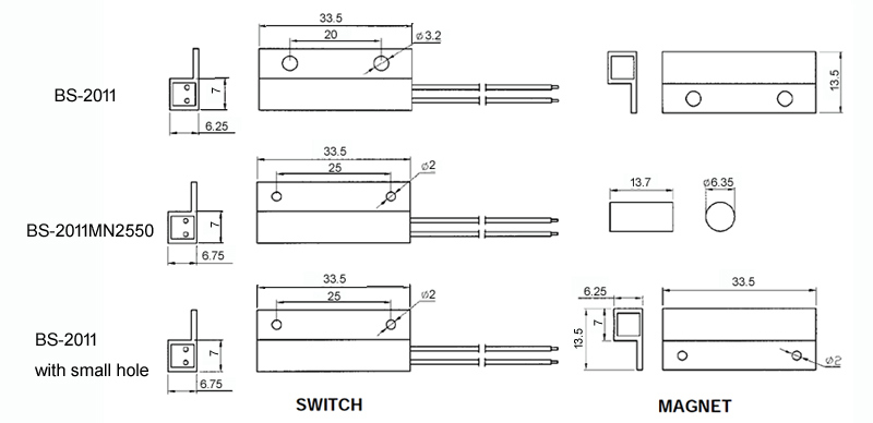 Product Features:Â
* Mini Stick-on contact with flange
* Side leads with #22AWG 18" length
* Adhesive and screw mount included
* Special leads on request
* Switches or magnets available seperately
* Resistor, Diode and Supervisory Loop available on request
* Colors: White, Brown, Grey
* Without Flange (BS-2051)
Order Information:
| Part Number | Loop Type | Reed Form |
Closed Gap [Inch(mm)] |
Depature Gap [Inch(mm)] |
Maximum Initial Contact Resistance (Ohm) |
Maximum Contact Rating(W) |
Maximum Switching Voltage (VDC/VAC) |
Maximum Switching Current(A) |
| BS-2011 | Closed | N/O | 1 (25) | 1.06 (27) | 0.150 | 10 | 100 | 0.5 |
| BS-2011MN2550 | Closed | N/O | 1 (25) | 1.1 (28) | 0.150 | 10 | 100 | 0.5 |
| BS-2011WG | Closed | N/O | 1 Â 1/4 (31) | Â | 0.150 | 10 | 100 | 0.5 |
| BS-2011A | Open | N/C | 1 (24) | Â | 0.150 | 3 | 30 | 0.2 |
| BS-2011C | Closed & Open | SPDT | 1 (24) | Â | 0.150 | 3 | 30 | 0.2 |
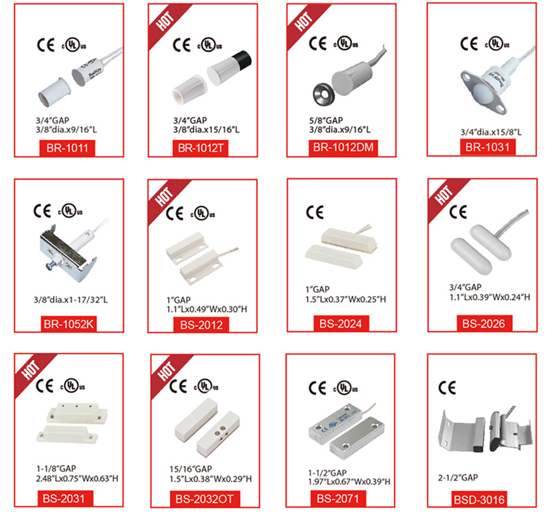
Related Products
Company Information
Â
Specification:Â
| Style: | Door Contact Alarm System Electric Magnetic Read Switch | Item: | BS-2011 |
| Color: | White, Brown, Grey | Material: | ABS |
| Cable: | Side leads with #22AWG 18" length | Loop Type: | closed |
| Reed Form: | N/O | Colsed Gap[Inch(mm)] | 1 (25) |
| Depature Gap[Inch(mm)] | 1.06 (27) | Maximum InitialContact Resistance(Ohm) | 0.150 |
| MaximumContact Rating(W) | 10 | Maximum Switching Voltage(VDC/VAC) | 100 |
| Maximum Switching Current(A) | 0.5 | Certificate | CE |
Door Contact Alarm System Electric Magnetic Read Switch
Dimension (mm):Product Features:Â
* Mini Stick-on contact with flange
* Side leads with #22AWG 18" length
* Adhesive and screw mount included
* Special leads on request
* Switches or magnets available seperately
* Resistor, Diode and Supervisory Loop available on request
* Colors: White, Brown, Grey
* Without Flange (BS-2051)
Order Information:
| Part Number | Loop Type | Reed Form |
Closed Gap [Inch(mm)] |
Depature Gap [Inch(mm)] |
Maximum Initial Contact Resistance (Ohm) |
Maximum Contact Rating(W) |
Maximum Switching Voltage (VDC/VAC) |
Maximum Switching Current(A) |
| BS-2011 | Closed | N/O | 1 (25) | 1.06 (27) | 0.150 | 10 | 100 | 0.5 |
| BS-2011MN2550 | Closed | N/O | 1 (25) | 1.1 (28) | 0.150 | 10 | 100 | 0.5 |
| BS-2011WG | Closed | N/O | 1 Â 1/4 (31) | Â | 0.150 | 10 | 100 | 0.5 |
| BS-2011A | Open | N/C | 1 (24) | Â | 0.150 | 3 | 30 | 0.2 |
| BS-2011C | Closed & Open | SPDT | 1 (24) | Â | 0.150 | 3 | 30 | 0.2 |
Related Products
Company Information
Â
The elevator guide shoe
Elevator guide shoe is a sliding part between elevator guide rail and car, what we call it guide shoe. It can fix the car on the guide rail and make car running up and down. Oil cup upper the elevator guide shoe that can reduce the friction of the shoe line and guide rail. There are four sets of guide shoes installed in each unit, respectively on both sides of the upper beam and under the safety clamp seat at the bottom of the car; and also four sets counter weight guide shoes are mounted on the bottom and top of the beam.
The guide shoes fixed on the car can move up and down along the fixed guide rail installed on the wall of the well way of the building to prevent the car from deviating or swinging in operation.
Guide shoe installation requirements
The installation method of guide shoe is to put it on the installation position of the guide rail of the car frame. After finding the right position, use the bolt fix it on the car guide rail frame. The installation must meet the following requirements:
- When the upper and lower guide shoes are installed in the right position, they should be on the same vertical line. No slant or deflection is allowed. Both roller guide shoes and fixed guide shoes same requirement.
- Fixed guide shoes are mainly used for FOVF units, the clearance between the two sides should be consistent, and the clearance between the inner lining and the rail top should be within O. 5 ~ 2 mm
-


Guide shoe,elevator Guide shoe,lift Guide shoe,casting Guide shoe liner
Suzhou Keffran Parts Co.,ltd , https://www.keffran-elevatorsmart.com