Electric pump downhole installation steps

Electric pump downhole installation steps 0. Acceptance of the unit: go to the logistics company to carefully check the acceptance of the cable jacket to see if there is no damage. Whether the unit is broken. 1. Handling: Loading and unloading car to be careful, so as not to damage the unit's concentricity or break the cable insulation. 2. Machine pump into one of the electric pump inspection process prior to the well: A. disassemble the network, use the pry bar toggle coupling should be flexible, B. See step 3. C. Place the unit on the outlet of the pump and add detergent powder water. At the same time, slightly move the motor start button to observe the steering of the pump. The time should not exceed 3 seconds, and the mark should be continued. 3. Pump split body assembly steps: A. Installation of the unit vertical stand, open the vent hole and water injection hole, be sure to be two water blocking are open, fill the water will fill and plug the water plug, observe the motor Is there a water leakage phenomenon, such as the phenomenon of water leakage must not go down, the reason may be bump in the transport process should be promptly contact the agents or manufacturers to discuss until no leak (observe 10-15 minutes). Then shake the motor insulation resistance, its value is not low and 50 megohms. B. bandage cable connector, wrapped and then try the motor steering, motor steering in the direction of the arrow marked on the pump is consistent, and make the follow-up mark. 4. On-site assembly: Assembly step A. The pump casing removed to expose the top of the impeller, B. Impeller rotation by hand to see if it is flexible C. Pulling the impeller in the direction of the pump shaft to observe the total amount of the impeller up and down the total channeling (general QJ pump 4 -6 mm) D. Install the coupling and motor together into one so that the motor shaft and the pump shaft head tight not allow a gap. E. See the impeller up and down the amount of clearance, it should be in the middle of the total amount of channeling (tolerance ± 0.5 mm). F. deviations of greater than 0.5 mm with adjusting shims to adjust to the middle of the manual rotation of the impeller should be flexible. G. Then drill the top hole of the coupling, tighten the top wire to install the upper shell. H. Once again use the pry bar toggle the coupling should be flexible and fit for a week. 5. The crew went down well: Before hanging down, use a rope to hang a round log with the same length of the unit (the diameter is equal to the maximum outer diameter of the unit) to test whether the test well pipe is straight. In order to avoid stuck wells when the next crew. (Especially the new wells under the first pump). 6. Banding of cables: The cables should be bound to the pipe with insulated cable tie, do not use wire. 7. Unit Control and Startup: Control Equipment Selection. Motor power × 1.2-1.4 times = control cabinet power. Control cabinet to have phase, overload, over current and short circuit protection. After the wells have been installed, the test machine is started. The start-up time is 10-25 seconds depending on the motor power. The start-up time of the high-power motor should be relatively long. Check if the current is overloaded and the three-phase current is balanced. And feedback manufacturers as a basis for warranty. 8. Overload, overcurrent, phase loss, short circuit, sensitivity debugging: This step is very important, please install the staff to debug carefully. A. Overload overcurrent debugging: The thermal relay current adjustment knob, slowly smaller than the actual operating current direction of rotation, each rotating a small scale, at intervals of 2 minutes until the thermal relay stop working until the unit. Then reverse the rotation a little scale can be. B. phase loss sensitivity debugging: the unit to start again, and one by one to disconnect the switch fuse switch unit, the unit is in two-phase power state. Observe if the thermal relay shuts off the control power within 5 seconds. C. Short circuit test: This step is usually to rely on the power supply system to protect the air switch. Generally not for field test (more dangerous) requires the power supply system must be equipped with air switch (air switch model preferred DW10, second choice DZ). The above eight units please use the installation and commissioning personnel, electrical and mechanical maintenance personnel carefully read!

Vanity Light

Vanity Light is a type of Lighting Fixture used in bathrooms or dressing rooms, typically installed above mirrors or vanities to provide sufficient illumination for the face and body. These Lighting Product typically consist of multiple bulbs, which can be LED or traditional incandescent bulbs, and can come in various designs and styles to suit different decor styles. Our Indoor Wall Light Bathroom Vanity Lighting is ideal for bathroom vanity, kitchen, mirror cabinet, a doorway or entryway, a living room.Indoor Wall Light
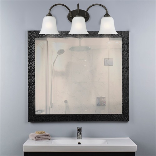
Vanity Light

Vanity Light,Bath Vanity Light,Vanity Lights,Bathroom Vanity Lighting

Zhengdong Lighting Co., Ltd. , https://www.zdlightingfixture.com